High Speed Flash “Tripwire”
Instructions for your DIY Flash trigger
Disclaimer: This guide is provided for educational and entertainment purposes only. Working with electronic circuits, power rails, and camera flash equipment carries inherent risks. Any mistakes or incorrect wiring can permanently damage your flash unit, camera equipment, or Arduino components. Please follow all assembly instructions carefully, double-check your connections before applying power, and proceed entirely at your own risk.
What You’ll Need - Laser Version - IR Version - Build Both
Parts for Both Builds
Arduino nano V3.0 $15.99: https://amzn.to/4zRN8RT
Bread board $7.19: https://amzn.to/4d48b9R
Jump Wire Kit $8.99: https://amzn.to/4gGGuEY
Breadboard Jumper Wires $9.99: https://amzn.to/467SJG0
PC817 Optocoupler$7.99 : https://amzn.to/4qXnAyC
10k Ohm Resistor ( for laser beam) $5.99: https://amzn.to/4qXztV5
220 Ohm Resistor $5.99 : https://amzn.to/4xchzzE
10k Ohm Potentiometer $7.99 https://amzn.to/4zUmHe2
IR Break Beam LED Sensor $9.99: https://amzn.to/3SuUIRD
5mm Photo Transistor (for laser beam) $5.79: https://amzn.to/4gOWlBI
3.5mm Mono Cable $8.95: https://amzn.to/4idVjBs
Laser Cat Toy $10: https://amzn.to/3STmyXN
5V Power Bank $10: https://amzn.to/4xEfyNH
Electrical Tape $2.98: https://amzn.to/4zXQ0fI
Build For Infra Red Trigger
Arduino nano V3.0 $15.99: https://amzn.to/4zRN8RT
Bread board $7.19: https://amzn.to/4d48b9R
Jump Wire Kit $8.99: https://amzn.to/4gGGuEY
Breadboard Jumper Wires $9.99: https://amzn.to/467SJG0
PC817 Optocoupler$7.99 : https://amzn.to/4qXnAyC
220 Ohm Resistor $5.99 : https://amzn.to/4xchzzE
10k Ohm Potentiometer $7.99 https://amzn.to/4zUmHe2
IR Break Beam LED Sensor $9.99: https://amzn.to/3SuUIRD
3.5mm Mono Cable $8.95: https://amzn.to/4idVjBs
5V Power Bank $10: https://amzn.to/4xEfyNH
Electrical Tape $2.98: https://amzn.to/4zXQ0fI
First things first.
How to Use the Bread Board:
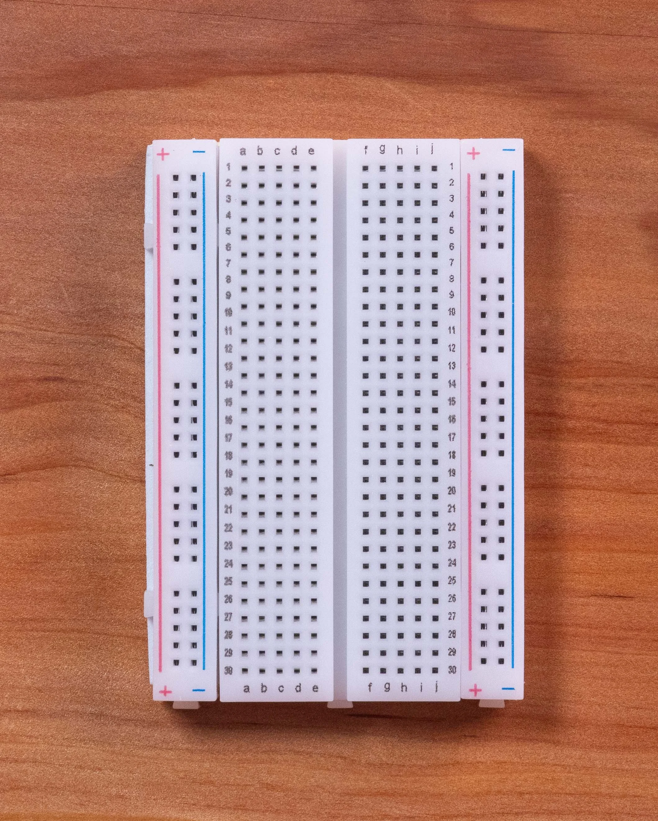
Power Rails (Outer Columns): The long outer columns marked with red (+) and blue (-) lines are connected vertically all the way up and down the board. If you plug power into any hole in the + column, every other hole in that same vertical column shares that power.
Middle Rows (Component Area): The numbered rows (1 through 30) with letters a through e on the left and f through j on the right are connected horizontally in groups of five. For example, holes 1a, 1b, 1c, 1d, and 1e are all wired together as a single node, but they are not connected across the middle to 1f–1j.
The Center Trench: The gap running down the middle of the board separates the left-side rows from the right-side rows. This allows you to place chips (like your PC817 optocoupler or Arduino Nano) across the trench so their left and right pins don't short-circuit into each other.
Infrared (IR) Sensor Version
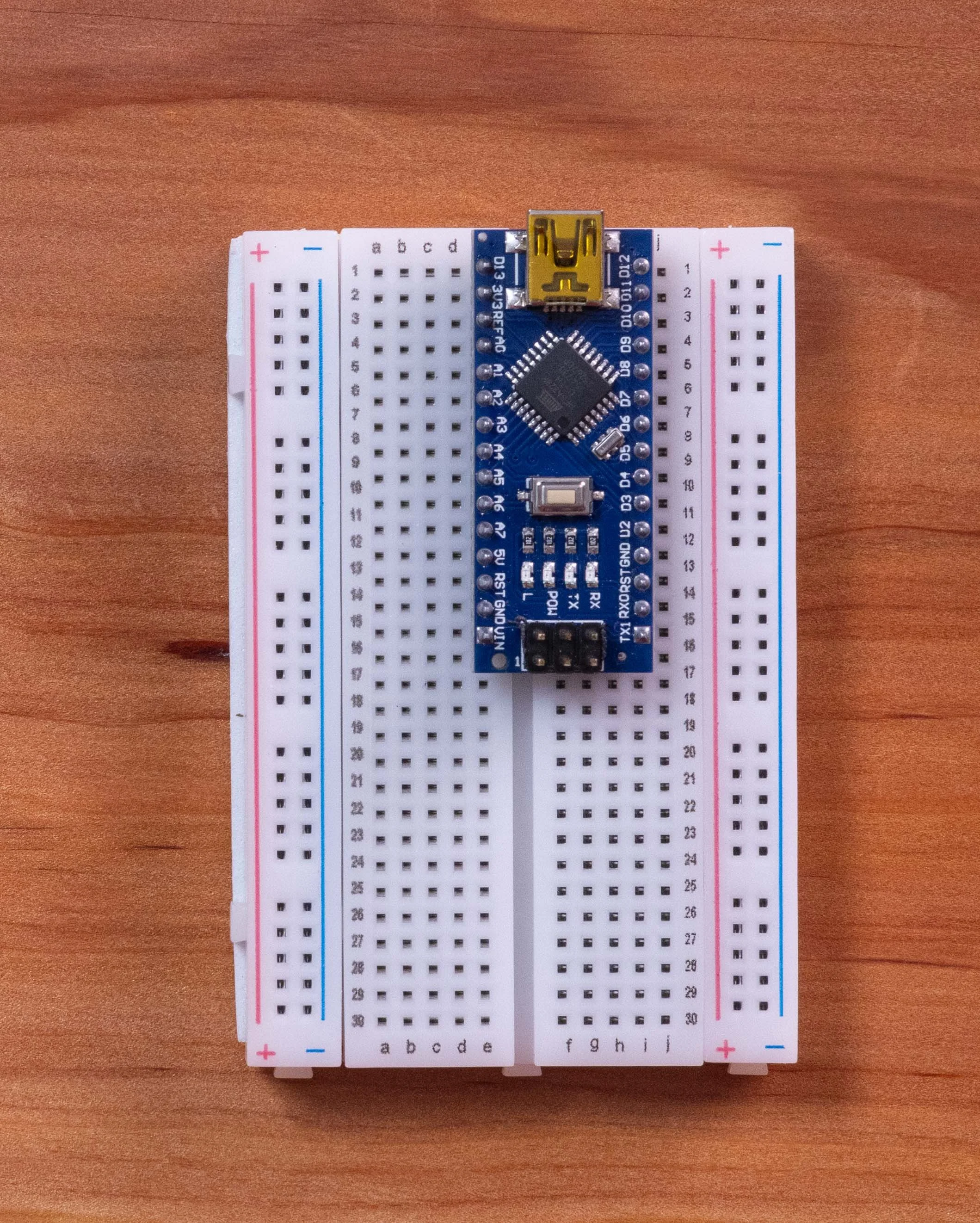
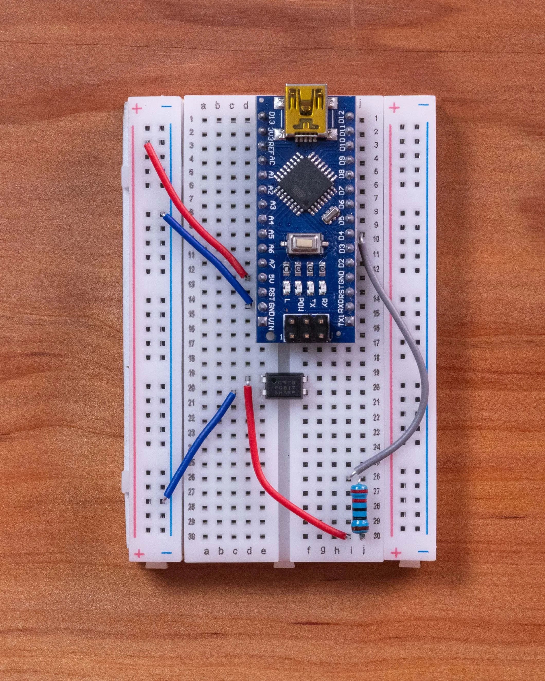
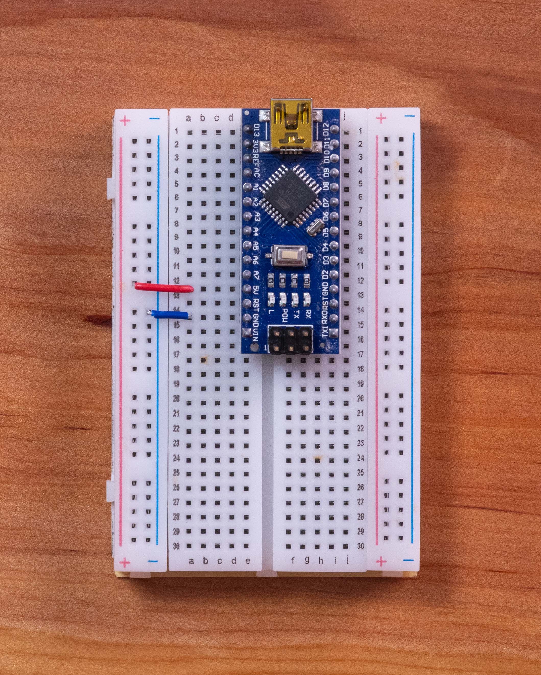
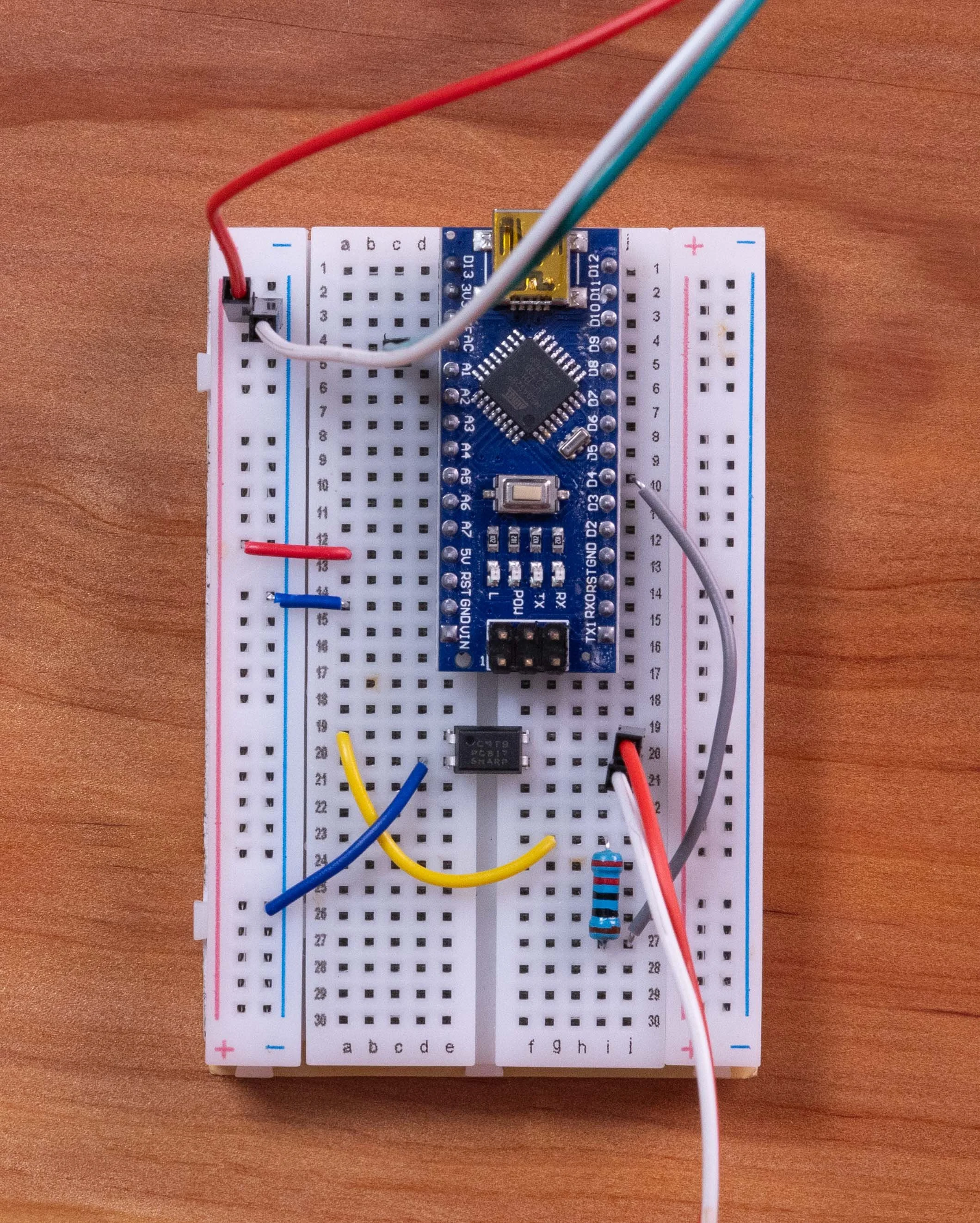
Start by plugging your Arduino with the USB power port at the edge of the Bread board. Start on row 1 column E. This with cover every pin from E1 to E15 and not he other side of the center trench with I-1 to I-15
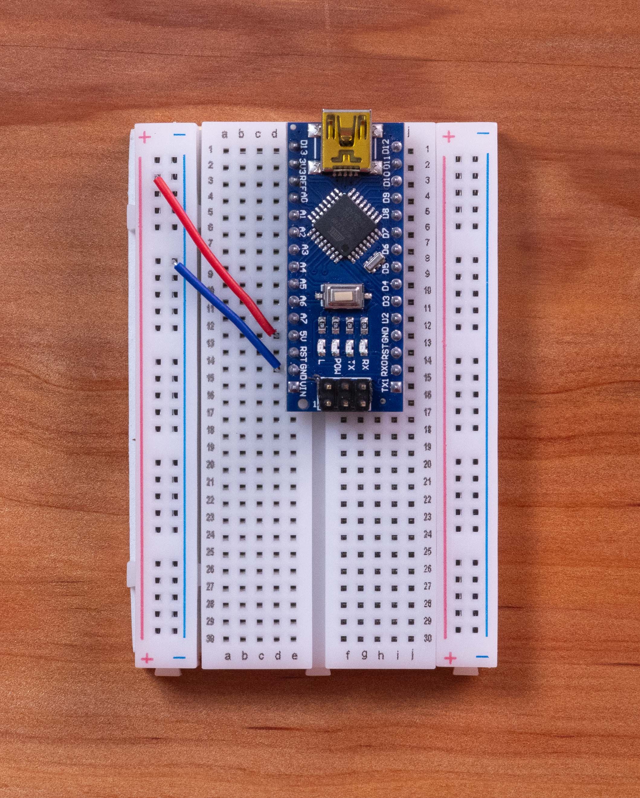
1.Let’s power the Bread Board
Run a jumper wire from the 5V pin on the Arduino Nano to the red (+) power rail on the breadboard.
Run a jumper wire from the GND pin on the Nano to the blue (–) ground rail.
2.The Output Circuit (PC817 Optocoupler & Flash Connection)
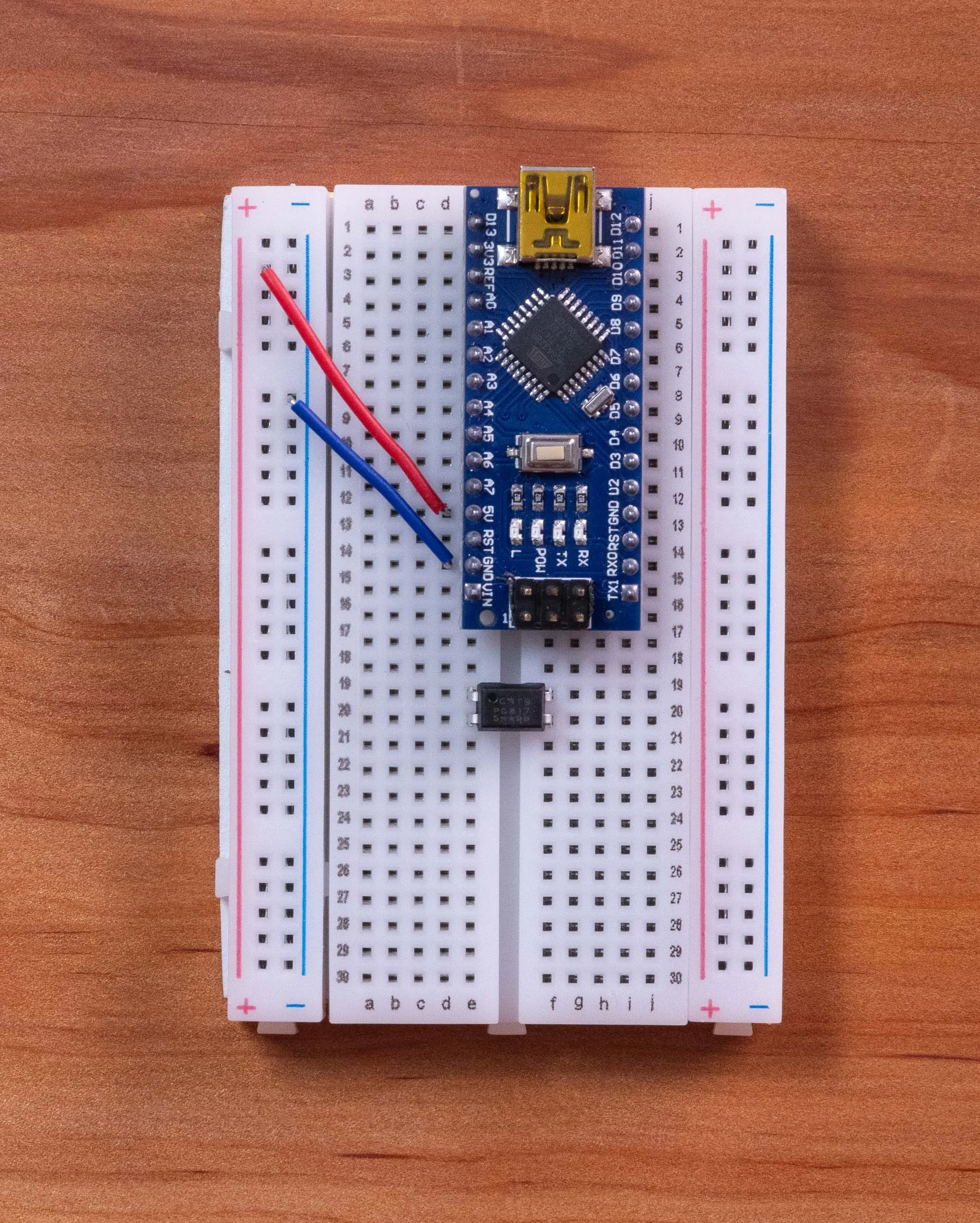
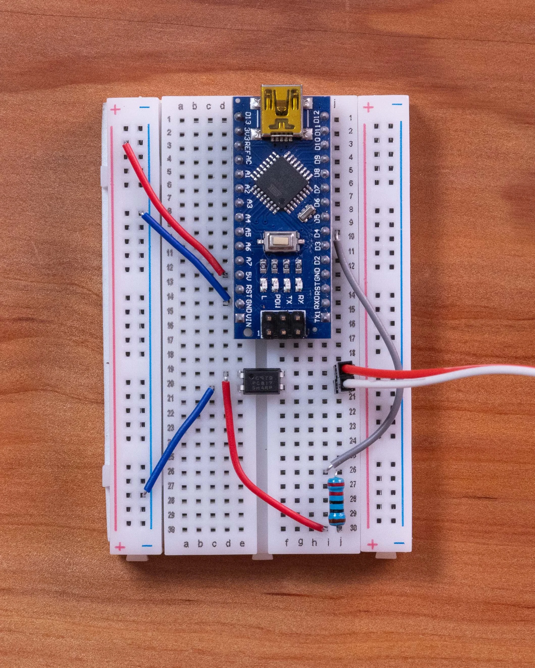
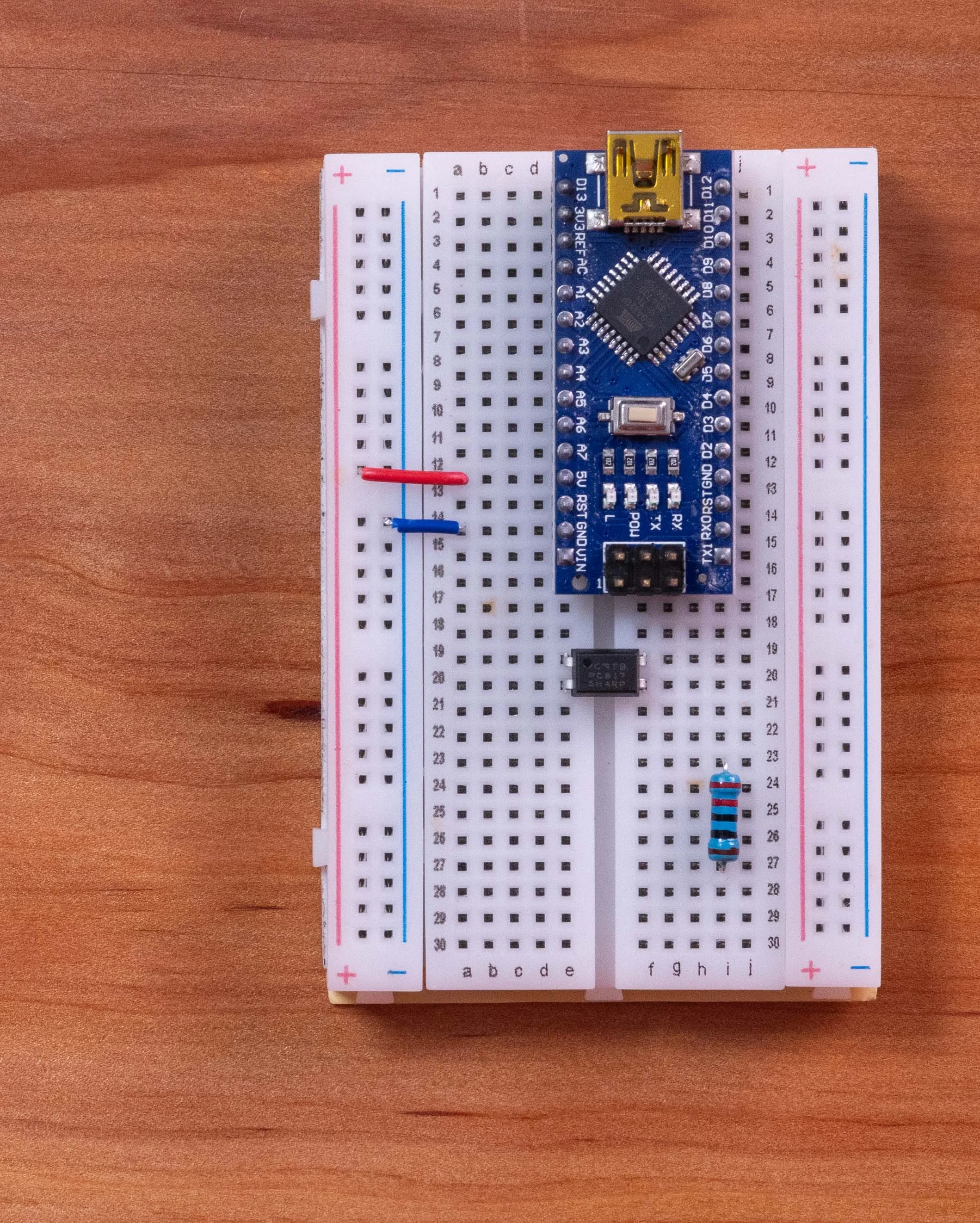
Insert the PC817 optocoupler across the center trench of the breadboard.
The optocoupler has a small dot on one of the corners, that is pin one. Place that for on the upper left corner so that it connects to E19, then Pint 2 is just below it on E20, Pin 3 is on F19 and Pin 4 will be on F20
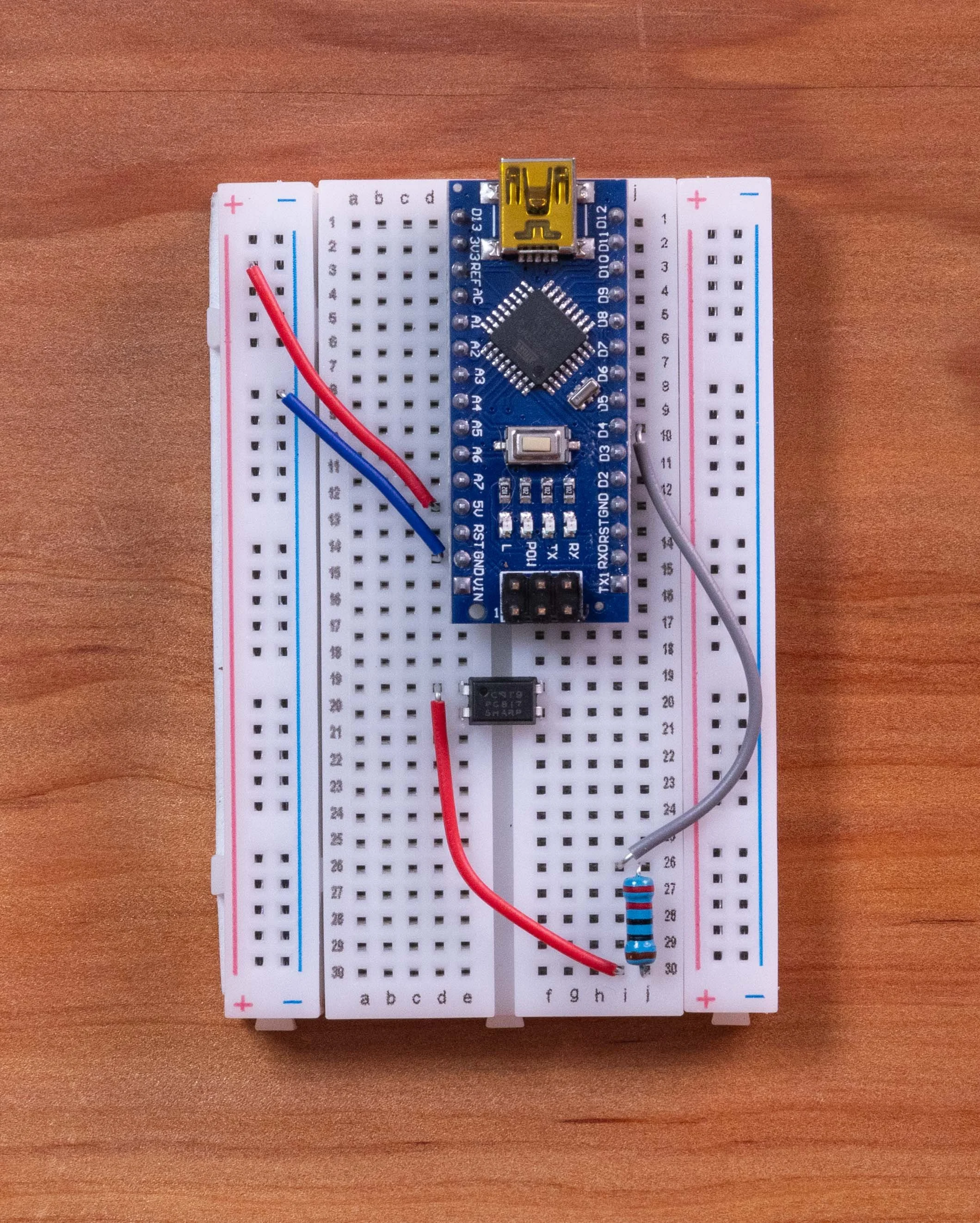
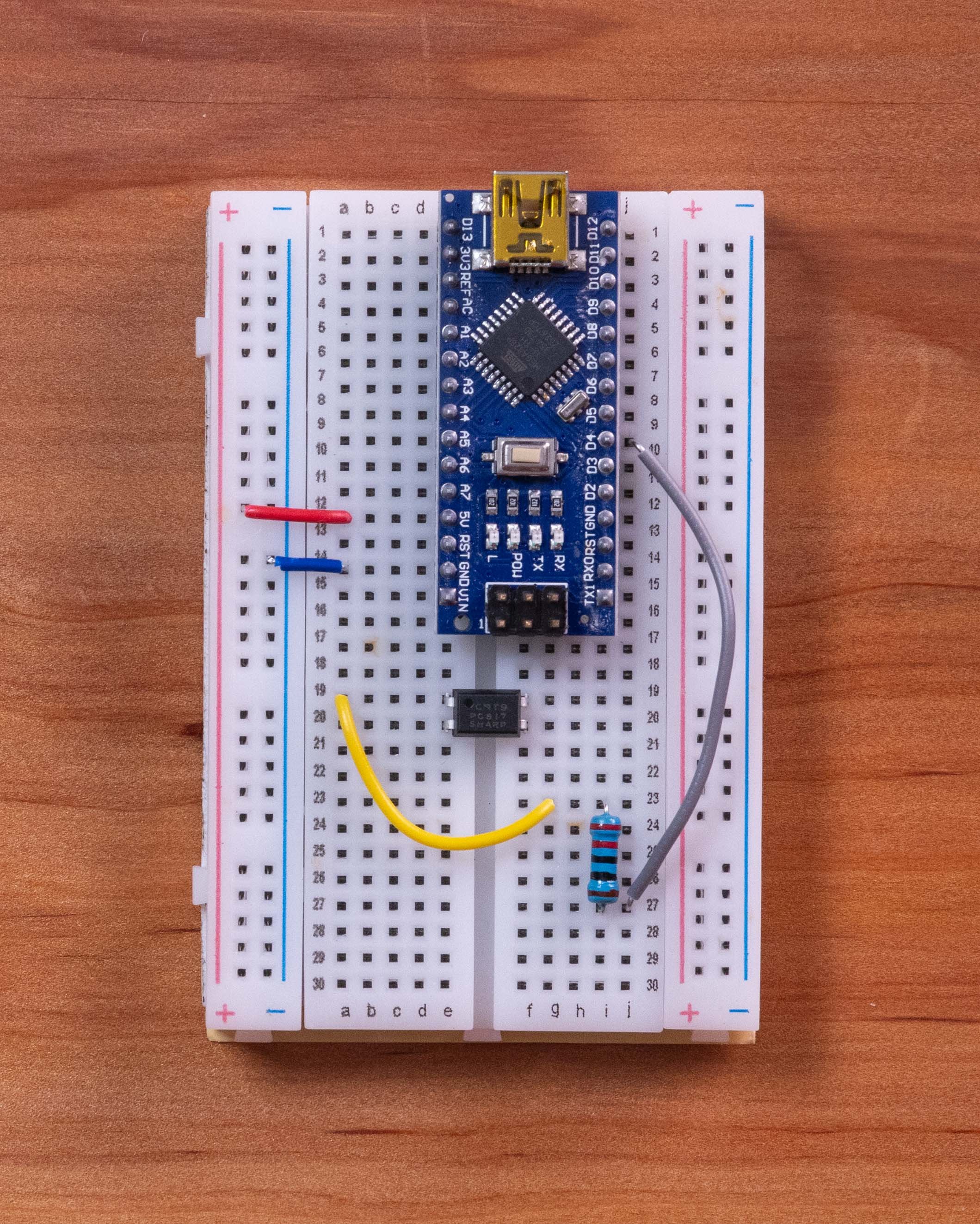
Connect a 220 ohm resistor from Nano digital pin D4 of the Arduino to Pin 1 of the PC817.
I chose to cut the legs of the resistor so that it doesn’t stick up as tall on the breadboard.
Place the 220 ohm resistor out of the way one leg on I-25 and the other on I-29 and use jump wires to complete the connection.
Now you can run a Jumper wire form Pin D4 of the Arduino, to the bottom leg of the 220ohm of the resistor and a second jump wire form the other leg of the 220 ohm to Pin 1 of the PC817 to complete the circuit.
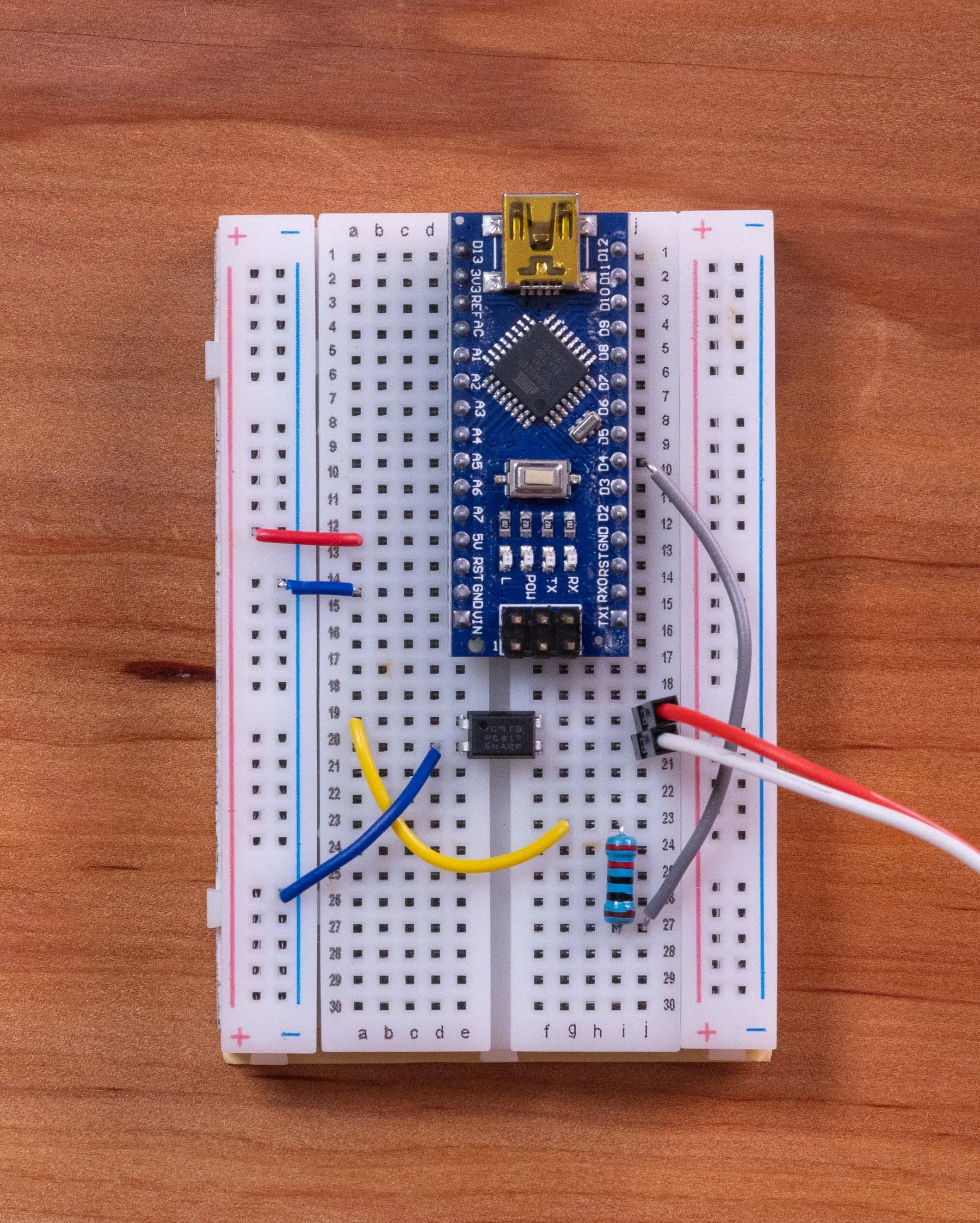
Run a jumper wire from Pin 2 of the PC817 to the blue (–) ground rail.
Connect your flash trigger wires: insert the red wire into the row for Pin 3, and the white wire directly below it into the row for Pin 4. (Cut one end of the 3.5mm jack and splice jumper wires to make an easier connection.
3.The Delay Potentiometer Knob
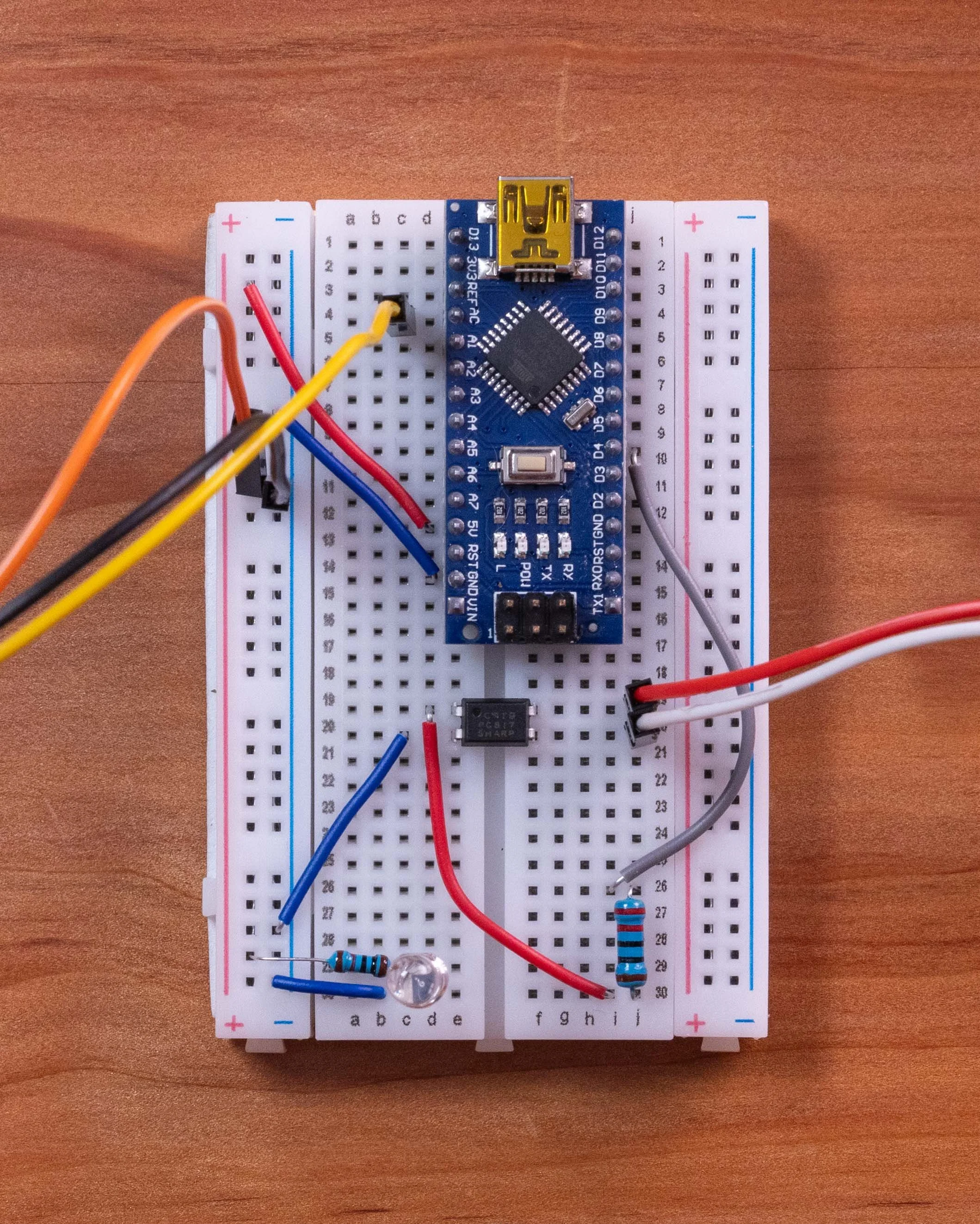
The Knob has 3 pins, use jumper wires and tape to hold them in place and extend them so that you can reach the proper ports. You will see a small notch on the upper part of the potentiometer.
Connect the left pin of the 10K potentiometer to the red (+) power rail.
Connect the right pin of the potentiometer to the blue (–) ground rail.
Connect the middle wiper pin directly to analog pin A0 on the Nano.
4.The 3-Wire IR Receiver Module Circuit
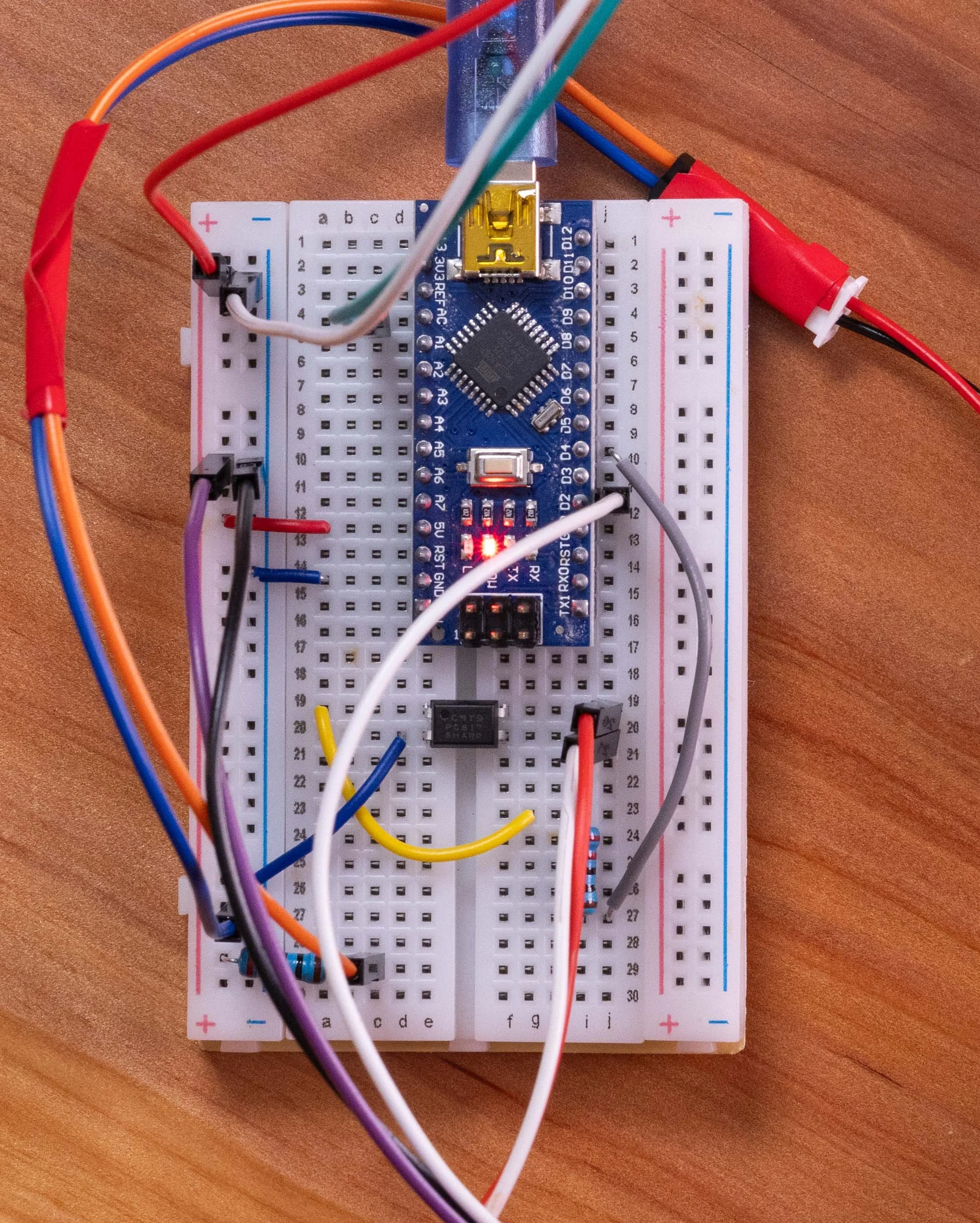
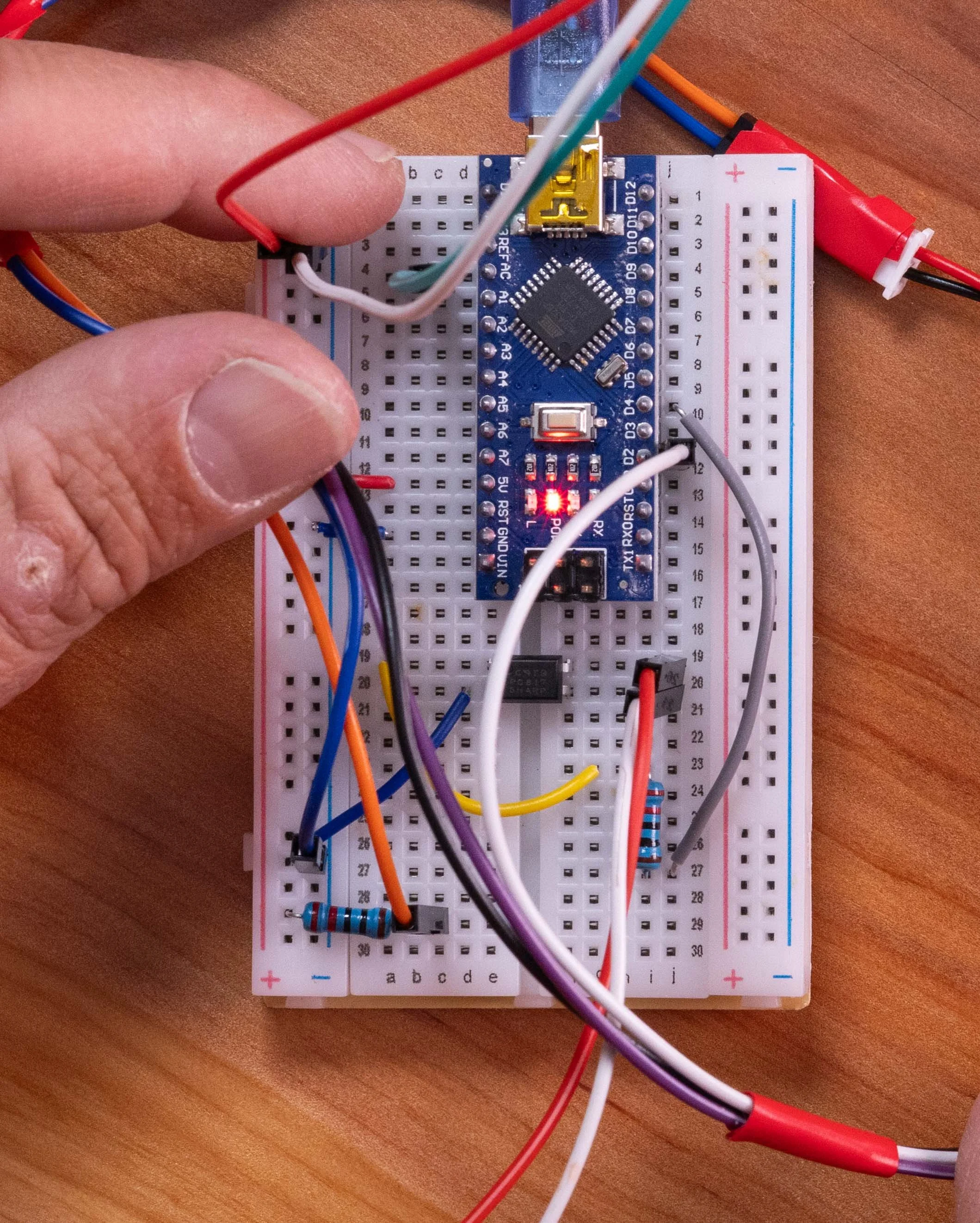
Connect the VCC (red wire) of the IR receiver module to the red (+) power rail.
Connect the GND (Black wire) of the IR receiver module to the blue (–) ground rail.
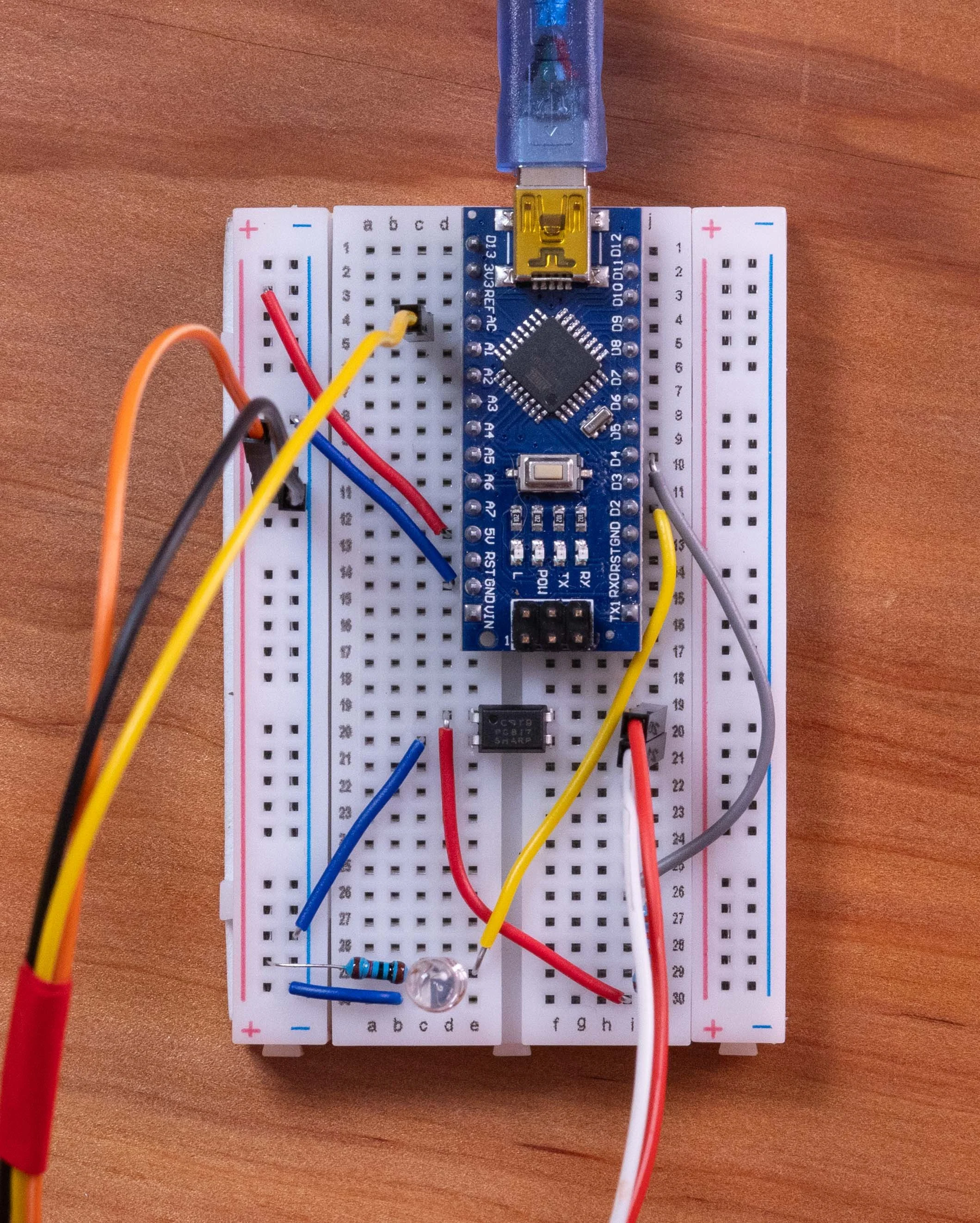
Connect the OUT/DO signal (White wire) directly into digital pin D2 on the Nano (no external pull-up resistor required).
5.The 2 Wire IR Emitter Module Circuit
Take a second 220ohm resistor plug one leg directly to the red (+)5v Power Rail. And the other leg to an empty spot on the board, lets use the bottom A30
Connect the red (positive) to the this new resistor power row like B30
Connect the black wire of (negative) to the blue (–) ground rail.
You can verify this step was successful by looking at the IR emitter through a smartphone camera while the Arduino is powered on to see if the LED glows faintly.
If you don’t use the second 220ohm resistor you could potentially burn up the emitter Code For IR sensor.
Once you upload the code to your Arduino Nano, you can power the circuit using a 5v power bank and start testing your flash trigger.
Code
Download Arduino IDE. Using a Data Transfer USB Mini cable Connect the Arduino Nano V3 to your computer download necessary firmware if necessary. Then select your device, make sure you have Arduino Nano selected.
Copy and Paste below the dotted Line.
…………………………………………………………………….
const int sensorPin = 2; // IR sensor output
const int triggerPin = 4; // PC817 input
const int potPin = A0; // Delay potentiometer
void setup() {
pinMode(sensorPin, INPUT);
pinMode(triggerPin, OUTPUT);
// Make sure flash is OFF at startup
digitalWrite(triggerPin, LOW);
Serial.begin(9600);
}
void loop() {
// Read potentiometer
int potValue = analogRead(potPin);
// Convert knob position to 1–500 ms delay
int flashDelay = map(potValue, 0, 1023, 1, 500);
// Read IR sensor
int sensorState = digitalRead(sensorPin);
// LOW = beam broken
if (sensorState == LOW) {
Serial.print("BEAM BROKEN! Delay: ");
Serial.print(flashDelay);
Serial.println(" ms");
// Wait for selected delay
delay(flashDelay);
// Fire the flash
digitalWrite(triggerPin, HIGH);
delay(10);
digitalWrite(triggerPin, LOW);
Serial.println("FLASH FIRED");
// LOCKOUT: ignore the sensor for 1 second
Serial.println("1 second lockout...");
delay(1000);
// Wait for the beam to be restored
while (digitalRead(sensorPin) == LOW) {
delay(1);
}
Serial.println("Beam restored. Ready for next drop.");
}
}
Build For Laser Trigger
Arduino nano V3.0 $15.99: https://amzn.to/4zRN8RT
Bread board $7.19: https://amzn.to/4d48b9R
Jump Wire Kit $8.99: https://amzn.to/4gGGuEY
Breadboard Jumper Wires $9.99: https://amzn.to/467SJG0
PC817 Optocoupler$7.99 : https://amzn.to/4qXnAyC
10k Ohm Resistor ( for laser beam) $5.99: https://amzn.to/4qXztV5
220 Ohm Resistor $5.99 : https://amzn.to/4xchzzE
10k Ohm Potentiometer $7.99 https://amzn.to/4zUmHe2
5mm Photo Transistor (for laser beam) $5.79: https://amzn.to/4gOWlBI
3.5mm Mono Cable $8.95: https://amzn.to/4idVjBs
Laser Cat Toy $10: https://amzn.to/3STmyXN
5V Power Bank $10: https://amzn.to/4xEfyNH
Electrical Tape $2.98: https://amzn.to/4zXQ0fI
Visible Laser Version
Start by plugging your Arduino with the USB port at the edge of the breadboard, straddling the center trench from rows 1 to 15 (with the left pins plugged into column E and the right pins plugged into column I
1. Let’s power the breadboard:
Run a jumper wire from the 5V pin on the Arduino Nano to the red (+) power rail on the breadboard.
Run a jumper wire from the GND pin on the Nano to the blue (–) ground rail.
2. The Output Circuit (PC817 Optocoupler & Flash Connection)
Insert the PC817 optocoupler across the center trench of the breadboard. The dot marks Pin 1: place it so Pin 1 connects to E19, Pin 2 to E20, Pin 3 to F19, and Pin 4 to F20.
Connect a 220ohm resistor from the Arduino pin D4 to Pin 1 of the PC817
Run a jumper wire from Pin 2 of the PC817 to the blue (–) ground rail.
Connect your flash trigger wires: insert the red wire into the breadboard row for Pin 3, and the white wire directly below it into the row for Pin 4.(Cut one end of the 3.5mm jack and splice jumper wires to make an easier connection.)
3.The Delay Potentiometer Knob.
There is a notch on the housing/base of the knob. That is the upper side, from here one pin is in the middle and on the lower part you have your left and right pins. use jumper wires to extend them to the proper ports. and tape to hold them in place.
Connect the left pin of the 10K potentiometer to the red (+) power rail.
Connect the right pin of the potentiometer to the blue (–) ground rail.
Connect the middle wiper pin directly to analog pin A0 on the Nano.
4.The Laser Sensor Circuit (with 10K Pull-Up Resistor)
Insert a 10K ohm resistor from the red (+) power rail into an empty signal node row on the breadboard. (b-29)
Plug the short leg (collector) of the phototransistor into that same signal node row.(d-29)
Plug the long leg (emitter) of the phototransistor into the blue (–) ground rail using a jumper wire. (d-30 Short leg. then Jumper from c-30 to (-) on the power rail)
Run a jumper wire from that shared signal node row directly to digital pin D2 on the Nano. (c-29 to Nano d2)
Once you upload the code to your Arduino Nano, you can power the circuit using a 5v power bank and start testing your flash trigger.
Code
Download Arduino IDE. Using a Data Transfer USB Mini cable Connect the Arduino Nano V3 to your computer download necessary firmware if necessary. Then select your device, make sure you have Arduino Nano selected.
Copy and Paste below the dotted Line.
…………………………………………………………………….
const int sensorPin = 2; // Phototransistor signal (with 10K pull-up)
const int triggerPin = 4; // PC817 input
const int potPin = A0; // Delay potentiometer
void setup() {
pinMode(sensorPin, INPUT);
pinMode(triggerPin, OUTPUT);
// Make sure flash is OFF at startup
digitalWrite(triggerPin, LOW);
Serial.begin(9600);
}
void loop() {
// Read potentiometer
int potValue = analogRead(potPin);
// Convert knob position to 1–500 ms delay
int flashDelay = map(potValue, 0, 1023, 1, 500);
// Read laser sensor (Phototransistor with pull-up)
int sensorState = digitalRead(sensorPin);
// HIGH = laser beam broken
if (sensorState == HIGH) {
Serial.print("BEAM BROKEN! Delay: ");
Serial.print(flashDelay);
Serial.println(" ms");
// Wait for selected delay
delay(flashDelay);
// Fire the flash
digitalWrite(triggerPin, HIGH);
delay(10);
digitalWrite(triggerPin, LOW);
Serial.println("FLASH FIRED");
// LOCKOUT: ignore the sensor for 1 second
Serial.println("1 second lockout...");
delay(1000);
// Wait for the laser beam to be restored (goes back to LOW)
while (digitalRead(sensorPin) == HIGH) {
delay(1);
}
Serial.println("Beam restored. Ready for next drop.");
}
}